greenBOX Unboxed i10: greenBOX Nxt Quick Installation Guide
Welcome to Issue 10 of greenBOX Unboxed, our series that explores the features and settings of the greenBOX. As we hit this milestone, it's only fitting that we present something special. This edition stands out from the rest, offering an in-depth look at the installation process of the greenBOX Nxt system, complete with multiple instructional videos.
Summary
In this comprehensive guide, we'll walk you through the essential steps of installing and connecting the components of Ecogate's dust collection control system. From mounting the greenBOX Nxt to connecting gates in a daisy-chain configuration, we'll cover it all. You'll learn about:
Installing greenBOX Nxt: Mount the unit on a wall, connect power and network cables.
Ecogate Interface Board Terminals: Understand the Modbus ports for connecting gates and VFDs, and additional terminals for relays, inputs, and status lights.
Connecting Ecogate Master Cable: Use pluggable connectors to connect the cable to greenBOX Nxt Modbus ports.
Connecting Gates in Daisy-Chain: Connect gates using Ecogate Master cables and double ferrules, ensuring proper shielding and securing cables.
Connecting Last Gate and Terminating Resistor: Connect the last gate with a terminating resistor jumper to prevent signal interference.
Connecting Workstation Activity Sensor: Use Ecogate Volt Sensors to signal workstation activity and connect them to the gate's "Signal" input.
Connecting Status LED Light: Install the light, understand its indicators, and optionally connect the buzzer.
Connecting the Power Master VFD Control Wiring: Connect the low-voltage control wiring plus review terminal layout overview.
Checking Terminating Resistor Status: Use an ohmmeter to verify the terminating resistor status at gates and greenBOX Nxt.
PDF Download
This comprehensive guide covers all essential installation steps. For your convenience, we've also made the full user guides available for download. The links are provided below:
greenBOX Nxt, Ecogate Gates And Volt Sensors Quick Installation Guide
1. Installing Your greenBOX Nxt
Positioning and Mounting
Choose a convenient indoor wall location for the greenBOX Nxt, ensuring easy monitoring of dust collection system performance.
Mount the unit at eye level to facilitate viewing and touchscreen operation.
Secure the wall mounting frame to the chosen location.
Attach the greenBOX Nxt to the frame using the enclosure sockets and three screws located inside the cabinet.

Power and Connectivity
Power Supply: Connect a 120V AC power supply to the greenBOX Nxt.
Use a separate circuit with a dedicated breaker to isolate the system from potential equipment failures.
Network Connection: Attach a local network (LAN) Ethernet cable (CAT5 or CAT6) to the greenBOX Nxt.
This connection enables remote access and support capabilities.

2. Overview of Ecogate Interface Board Terminals
The Ecogate Interface Board is a crucial component of your greenBOX Nxt system. Let's explore its key terminals and their functions.
Modbus Ports
These ports connect Ecogate gates and Power Master VFDs to the greenBOX Nxt.
Each port can support up to 24 gates in a daisy-chain configuration.
If not all ports are needed for gates, you can dedicate one to VFDs.
VFDs can be added to gate daisy-chains if all ports are required.
Important Considerations:
The first and last devices in each Modbus daisy-chain must have a terminating resistor switched ON.
Blue terminating resistors on the greenBOX Nxt interface board come factory-enabled in the ON position.
For the last gate in each daisy-chain, add a terminating resistor jumper (provided in the plastic box).
Additional Terminals
The interface board also includes:
Terminals for relay outputs
Digital inputs
LED status light connection
Note: Digital input and relay contact functions are user-programmable (optional).
Recommended: Utilize the LED status light for system monitoring:
Green: All systems OK
Orange: Warning (e.g., filter pressure reached warning level)
Red: System error
3. Connecting Ecogate Master Cable to greenBOX Nxt Modbus Port
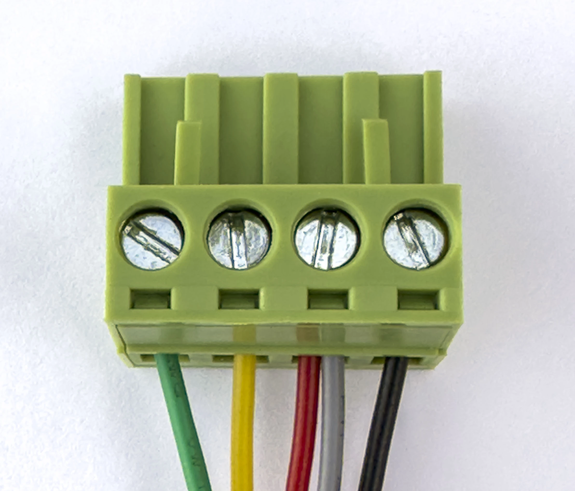
To connect the Ecogate Master cable to the greenBOX Nxt Modbus ports, use the included pluggable Phoenix screw connectors. Each connector has five terminals, which should be connected as follows:
+24V DC: Red wire
-24V DC: Black wire
Modbus A wire (positive): Blue wire
Modbus B wire (negative): White wire
Shielding: Silver uninsulated wire

Important Note on Shielding: The shielding wire is connected at the greenBOX and within the daisy-chain. However, it is NOT connected to the gate or VFD. This configuration prevents double grounding issues that can disrupt Modbus communication.
4. Connecting Gates in Daisy-Chain Using Ecogate Master Cable
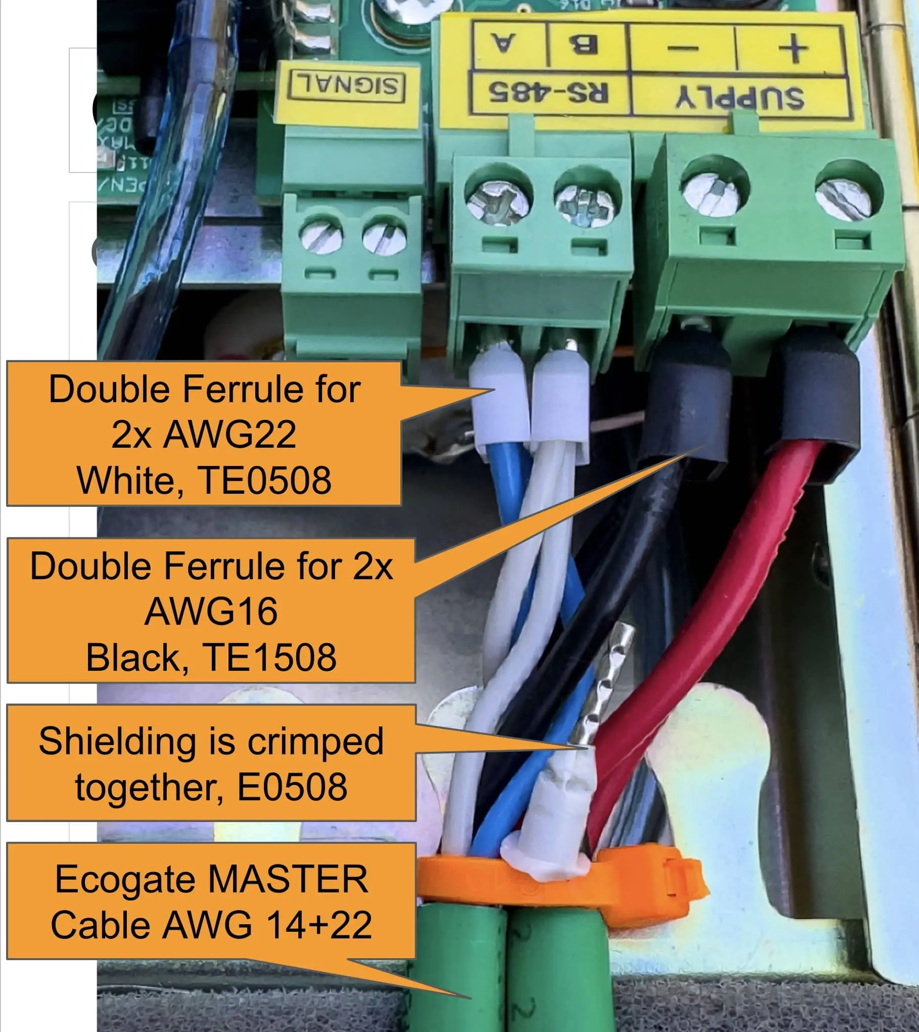
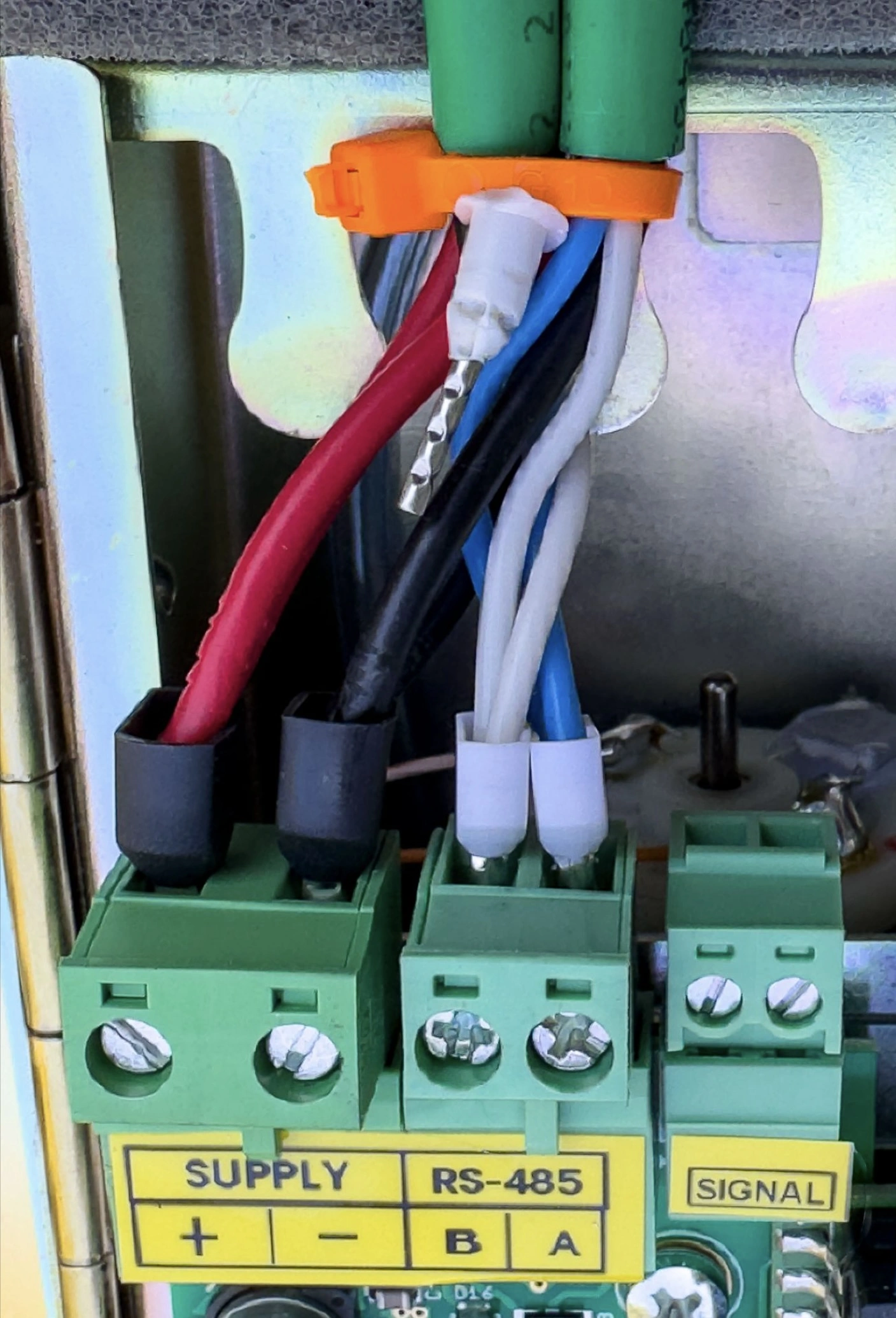
Connecting gates in a daisy-chain configuration requires attaching two Ecogate Master cables to each gate's connectors. Each gate features three Phoenix screw connectors for different functions, each with a unique size to prevent errors and accommodate various wire sizes.
Connection Process
24V DC Connection:
Use a black double ferrule for AWG16 wires (model TE1508).
For AWG14 wires from the Ecogate Master cable, cut half the strands before crimping as they won't fit this ferrule.
Note: Larger double ferrules for AWG14 wires won't fit the Phoenix screw terminal.
Modbus A and B Wires:
Use a white double ferrule for AWG22 wires (model TE0508).
Shielding Wire:
Do not connect the bare shielding wire to the gate to avoid double grounding.
Connect the shielding of both cables using a white ferrule for AWG22 wire (model E0508).
Ensure the shielding doesn't come into contact with the metal gate enclosure.
Secure the Cables:
Use cable ties to secure the cable to the gate motor enclosure, preventing accidental disconnection.
Left: Connecting gates in daisy-chain using Ecogate MASTER Cable and utilizing double ferrules
Right: +24V DC = Red wire, -24V DC= Black wire, Modbus A wire (positive) = Blue wire, Modbus B wire (negative) = White wire
Advantage of Daisy-Chained Cables
Even if terminals are disconnected from a gate, the power supply and Modbus communication to other gates in the daisy-chain remain uninterrupted.
Required Materials (per gate)
2 x Black double ferrule for AWG16 wires (model TE 1508)
2 x White double ferrule for AWG22 wires (model TE0508)
1 x White ferrule for AWG22 wire (model E0508)
2 x Cable tie 4" long
5. Connecting Last Gate in Daisy-Chain with Terminating Resistor
The connection process for the last gate in the daisy-chain is simplified, requiring only one Ecogate Master cable. However, it includes a crucial additional step: installing a terminating resistor jumper.
Cable Connection
Connect the wires to the two Phoenix screw connectors as follows:
+24V DC: Red wire
-24V DC: Black wire
Modbus A wire (positive): Blue wire
Modbus B wire (negative): White wire
Shielding: Cut the silver uninsulated wire; it is not connected.
Important: Secure the cable to the gate motor enclosure using a cable tie to prevent accidental disconnection.
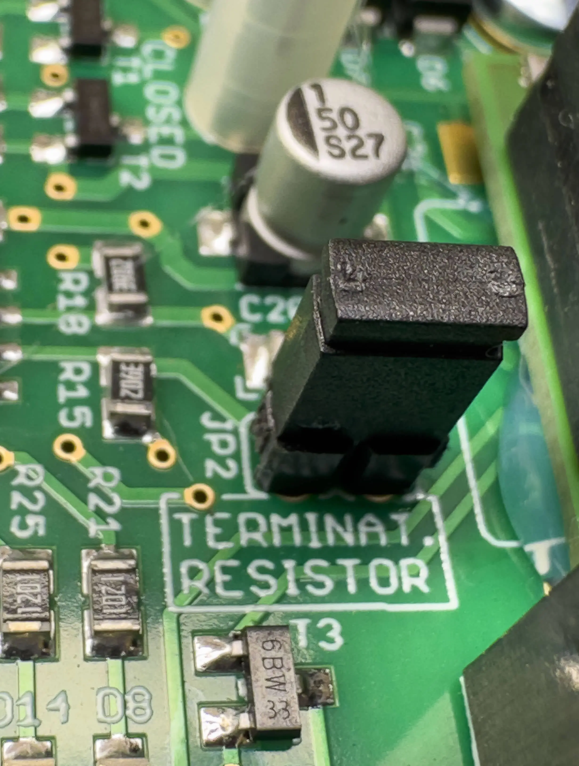
Left: Connecting last gate in daisy-chain; remember to connect terminating resistor jumper (top left at this picture). Right: Detail of black connected terminating resistor jumper
Terminating Resistor Jumper Installation
The last gate in the daisy-chain requires a terminating resistor jumper. This component is crucial for system performance:
It activates the terminating resistor on the PCB board.
Without it, the cable end reflects the Modbus signal, causing interference that can compromise communication quality and system reliability.
Terminating resistor jumpers are standard computer-type jumpers included with each greenBOX Nxt.
Install these jumpers at the end of every Modbus daisy-chain.
Remember: Proper installation of the terminating resistor jumper is essential for maintaining optimal system performance and reliability.
6. Connecting Workstation Activity Sensor to the Gate
Workstation Activity Sensor Recommendation
Ecogate recommends using Volt Sensors for workstation activity signals due to their easy installation and zero-configuration requirements. These sensors should be connected to the circuit that activates when the workstation needs dust collection.
For simple workstations (e.g., table saws): Connect the sensor input in parallel to the saw motor.
For complex CNC machines: Consult your local maintenance head for proper connection.
Volt Sensor Options
AC-DC Volt Sensor:
Input voltage range: 24-230 VAC or DC
AC Volt Sensor:
Input voltage range: 120-690 VAC
Safety Notes for AC Volt Sensor Connection
When connecting to AC power, connect between:
Two phase wires, OR
A phase wire and neutral
NEVER connect between a phase wire and ground.
Use Ecogate Sensor wire for connections. It's insulated for 600V, making it suitable for installation inside workstation electrical panels with typical voltages of 230V or 460V.
Volt Sensor Connection
Input: Connect to the workstation circuit that activates when dust collection is required.
Output: Connect to the gate's "Signal" input (polarity independent).

Troubleshooting Volt Sensors
Active Input: The "IN" indicator will be lit when the Volt sensor's input is active.
Active Output: If the output is connected to a powered gate and the input is active:
The "OUT" indicator on the sensor will be lit.
The yellow "SNS" indicator on the gate board will be lit.
Remember: Always prioritize safety when working with electrical connections. If you're unsure about any step, consult with a qualified electrician or Ecogate support.
7. Connecting Green-Orange-Red Status LED Light
The status LED light is a crucial component for monitoring your system's performance. Here's how to install and set it up:
Installation and Indicators
Install the status light in a visible location for easy system monitoring.
Light Indicators:
Green: All systems OK
Orange: Warning (e.g., filter pressure issue)
Red: System error
Optional Buzzer
The status light includes a built-in buzzer:
You can choose to connect or disconnect the buzzer (gray wire) based on your preference.
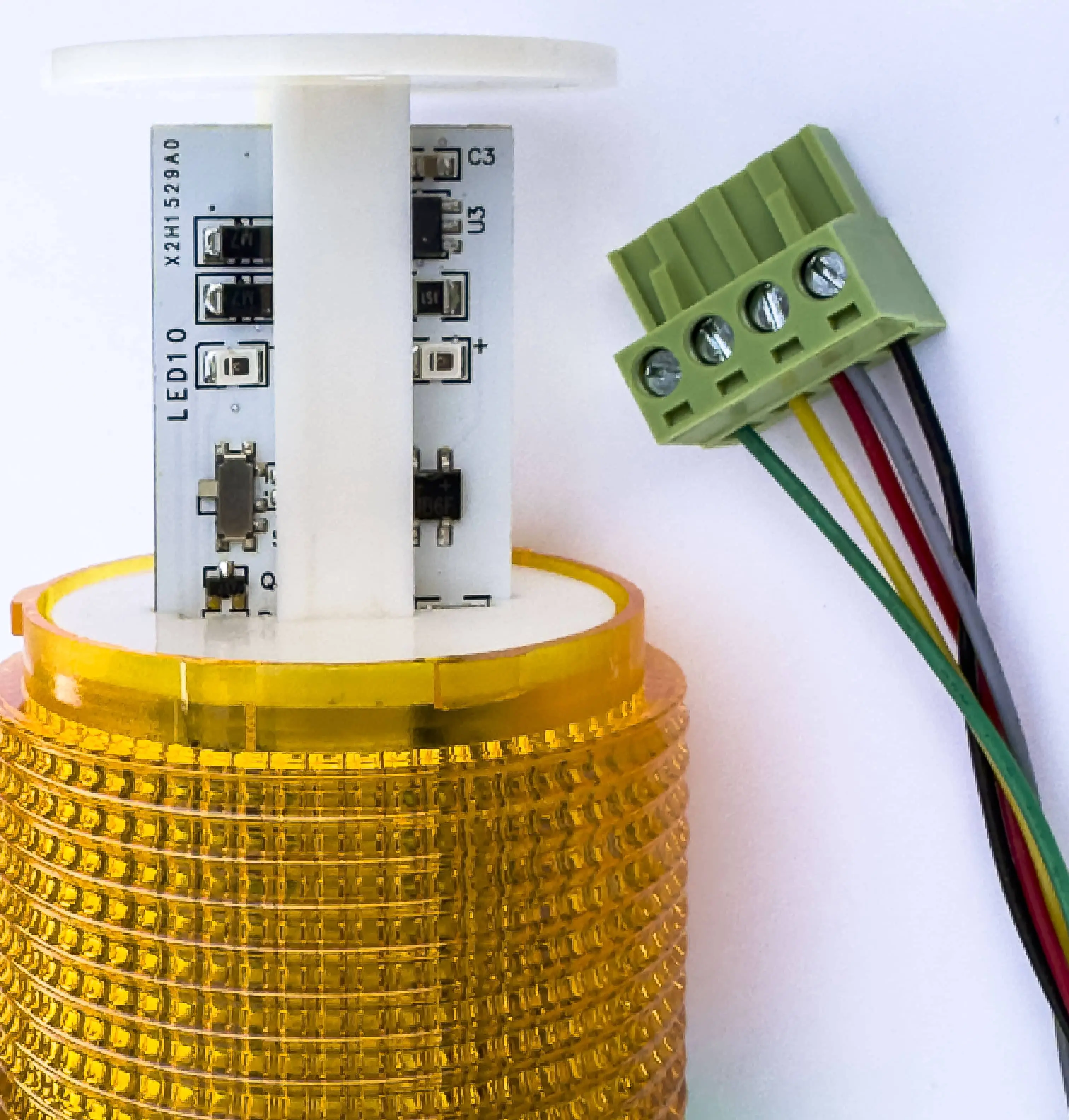
Fig. 10: Twist LED light cover counterclockwise to access the steady/flashing light selector.
Fig. 11: Status light wires from left: Green, Orange, Red + gray Buzzer, Black ground
Connection and Setup
Individual Outputs:
Green, orange, and red outputs provide 24V DC (max current limited to 0.37A).
Ground Connection:
The common black wire serves as ground.
Buzzer Connection:
If desired, connect the gray buzzer wire in parallel with the red light.
Customizing Light Behavior:
To access the steady/flashing light selector, twist individual LED light covers counterclockwise.
Remember: Proper installation and understanding of the status light indicators will help you quickly identify and respond to system status changes.
8. Connecting the Power Master VFD Control Wiring
This section provides a straightforward guide to connecting the low-voltage control wiring for your Power Master Variable Frequency Drive (VFD), a simple process when compared to all other VFDs.
Note: For detailed instructions on connecting 3-phase power to the VFD and fan motor, please refer to the separate Power Master VFD User and Installation Guide.
Understanding the Power Master VFD
The Power Master VFD is engineered with user-friendly features, including pluggable screw terminals and clearly labeled connections. This design simplifies the wiring process, allowing for quick and accurate installation.
Terminal Layout Overview
From right to left, the Power Master VFD terminals are organized as follows:
PX1: Modbus Communication
Function: Connects to the greenBOX Nxt via the Ecogate Master cable for Modbus communication.
Connection: Refer to the Ecogate Master Cable section for detailed wiring instructions.
PX2: Automatic Start/Stop Control (Optional)
Function: Enables automatic starting and stopping of the dust collector, reducing manual intervention.
Wiring: Connect the VFD’s START and STOP wires to the dust collector’s PLC control panel as outlined below.
PX3: Safety Devices Connection
Function: Integrates various safety devices that monitor and ensure the safe operation of the dust collection system.
Devices: Examples include spark detection systems, abort gates, non-return valves, fire/blast detection sensors, and dust collector error signals.
Note: Descriptions at the bottom of the terminals refer to the VFD signals to which each wire is connected. These are not Ecogate terminals.

From right to left: PX1 terminal (Modbus connection from greenBOX), PX2 (for automatic Start & Stop of the dust collector), and PX3 (all customer safeties can be connected here, including Enable signal from the dust collector).
Step-by-Step Wiring Instructions
PX1 Terminal: Modbus Communication
Locate the Ecogate Master Cable:
Identify the 5-wire Ecogate Master cable originating from the greenBOX Nxt.
Connect the Cable to PX1:
Match each wire to the corresponding terminal label:
+24V DC (RED)
-24V DC (BLACK)
Modbus A (BLUE)
Modbus B (WHITE)
Shielding (bare SILVER wire): Do not connect the shielding wire to the VFD’s ground (G) terminal to avoid double grounding.

From left to right: +24V DC (RED), -24V DC (BLACK), Modbus A (BLUE), Modbus B (WHITE), and shielding. Note that shielding is not connected to the G terminal on the right side (it should be connected at greenBOX terminal).
PX2 Terminal: Automatic Dust Collector Start/Stop (Optional)
Automate Dust Collection:
START Connection:
Connect the VFD’s START dry NO contact (labeled STRT) in parallel with the dust collector’s START button on the PLC.
STOP Connection:
Connect the VFD’s STOP dry NC contact (labeled STOP) in series with the dust collector’s STOP button on the PLC.
Alternative for Remote Start:
If your dust collector features a dedicated remote start input, utilize the VFD’s RUN wires instead of the START/STOP wires for enhanced control.
Manual Control Option:
To maintain manual control (not recommended), you may leave the PX2 terminal unconnected.

To start and stop the dust collector automatically, the dry NO contact START (labeled STRT - STRT) on the left should be connected in parallel to the dust collector PLC START button. The Dry NC contact STOP (labeled STOP - STOP) on the right should be connected in series with the dust collector PLC STOP button.
PX3 Terminal: Connecting Safety Devices
Mandatory Safety Connection:
ENABLE Signal:
Connect the dust collector PLC’s dry contact ENABLE output to the VFD’s ENABLE input on the PX3 terminal.
Function: Ensures the VFD operates only when the dust collector is running safely.
Additional Safety Inputs:
STOP Input:
Connect critical safety systems (e.g., fire alarms) to the STOP input.
Behavior: Triggers a manual reset at the control panel if activated.
AIR-LCK and TRN-PRT Inputs:
For monitoring airlocks and transport fans, connect current sensors with dry contact outputs.
Function: Provides detailed shutdown information on the VFD display.
Removing Default Jumpers:
By default, blue jumpers are installed on the additional safety inputs. Remove these jumpers before connecting any safety devices to ensure proper functionality.
Using Current Sensors for Airlock and Transport Fan:
For simpler dust collectors without a PLC, use current sensors with dry contact outputs to monitor the airlock and transport fan.
Connection: Connect these sensors to the AIR-LCK and TRN-PRT inputs respectively.

The terminal PX3 allows connecting up to four “customer safeties,” one of which is mandatory from the dust collector PLC. If the dust collector is running OK (without any issues), the dry contact (output from dust collector PLC) is closed. In case of any issues, this contact should open.
Switching Off the VFD’s Modbus Terminating Resistor
The Power Master VFD’s Modbus terminating resistor is enabled (ON) by default. If your VFD is not the last device in your Modbus network, you must disable this resistor to prevent communication issues. Follow these detailed steps to disable the terminating resistor:
Prepare the VFD:
Disconnect Power: Turn off the power to the VFD.
Disconnect from greenBOX: Unplug the PX1 terminal (this cuts power to the VFD’s processor).
Wait for Discharge: Wait for 5 minutes to allow the VFD’s capacitor to discharge completely.
Access the J3 DIP Switch:
Remove VFD Cover:
Locate the two star screws on the bottom left and right of the VFD.
Unscrew them and remove the plastic cover.
Find J3 Switch:
Look for the J3 DIP switch below the green Analog Output terminal and the gray Modbus terminal.
You’ll see two switches in the opening: J3 on top and J6 at the bottom.
Set the Switch to “Off”:
Identify Position:
The white selector on the J3 switch indicates the current setting:
Right: Resistor is ON
Left: Resistor is OFF
Move Selector:
Slide the white selector to the left to turn the resistor OFF.
Verify (Optional):
If you want to double-check your work, use an ohmmeter (with the VFD power still off):
Resistor OFF: You should measure a high resistance of about 168 kOhm between the Modbus A and B terminals.
Resistor ON: The resistance will be much lower, around 117 Ohm.
Reassemble:
Once the resistor is set correctly, replace the VFD’s plastic cover and secure it with the screws.
Reconnect the PX1 terminal and restore power to the VFD.

To access terminating resistor J3 switch: remove gray plastic cover of the VFD, locate J3 switch below the green Analog Output terminal and gray Modbus terminal. There are two switches in the opening: J3 on top, J6 at bottom. Top J3: if white selector is on right, it is ON, and OFF if it is on left.

With terminating resistor ON, resistance between Modbus A and B terminals is about 117 Ohm.

With terminating resistor OFF, resistance between Modbus A and B terminals is about 168 kOhm.
Important: You only need to disable the terminating resistor if your VFD is not the last device in your Modbus network. If you’re unsure, refer to the full VFD documentation or contact Ecogate support.
Safety Precautions
Voltage Levels: While most control wires use 24V DC, some dust collector control panels may operate at higher AC voltages (120V/230V/460V/575V). Always verify the voltage requirements and follow all safety standards to prevent accidents or injuries.
Power Isolation: Before making any connections, disconnect the power to the VFD to ensure a safe working environment.
Proper Termination: Ensure all connections are secure and that terminating resistors are correctly installed as outlined above to maintain reliable communication and system stability.
Finalizing the Installation
Double-Check Connections:
Review all wiring connections to ensure they match the terminal labels and follow the instructions precisely.
Restore Power:
Once all connections are verified, reconnect the power to the VFD and greenBOX Nxt.
Test the System:
Power on the system and observe the status indicators to confirm successful communication and operation of the VFD and connected safety devices.
Consult Documentation:
If issues arise, refer to the full Power Master VFD User and Installation Guide or contact Ecogate support for further assistance.raging the strengths of the blog format to enhance readability and engagement.
9. How to Check If Terminating Resistor at Gate and at greenBOX Nxt is On
Proper termination of your Modbus daisy-chain is crucial for reliable communication. The first and last devices in the chain (greenBOX Nxt, gates, VFDs) must have a terminating resistor enabled to prevent signal reflection and interference.
Verifying Terminating Resistor Status
To check the status using an ohmmeter:
Important: Disconnect the 120V AC power supply before testing.
At the Gate:
Connect the ohmmeter between the gate's Modbus A and B wires.
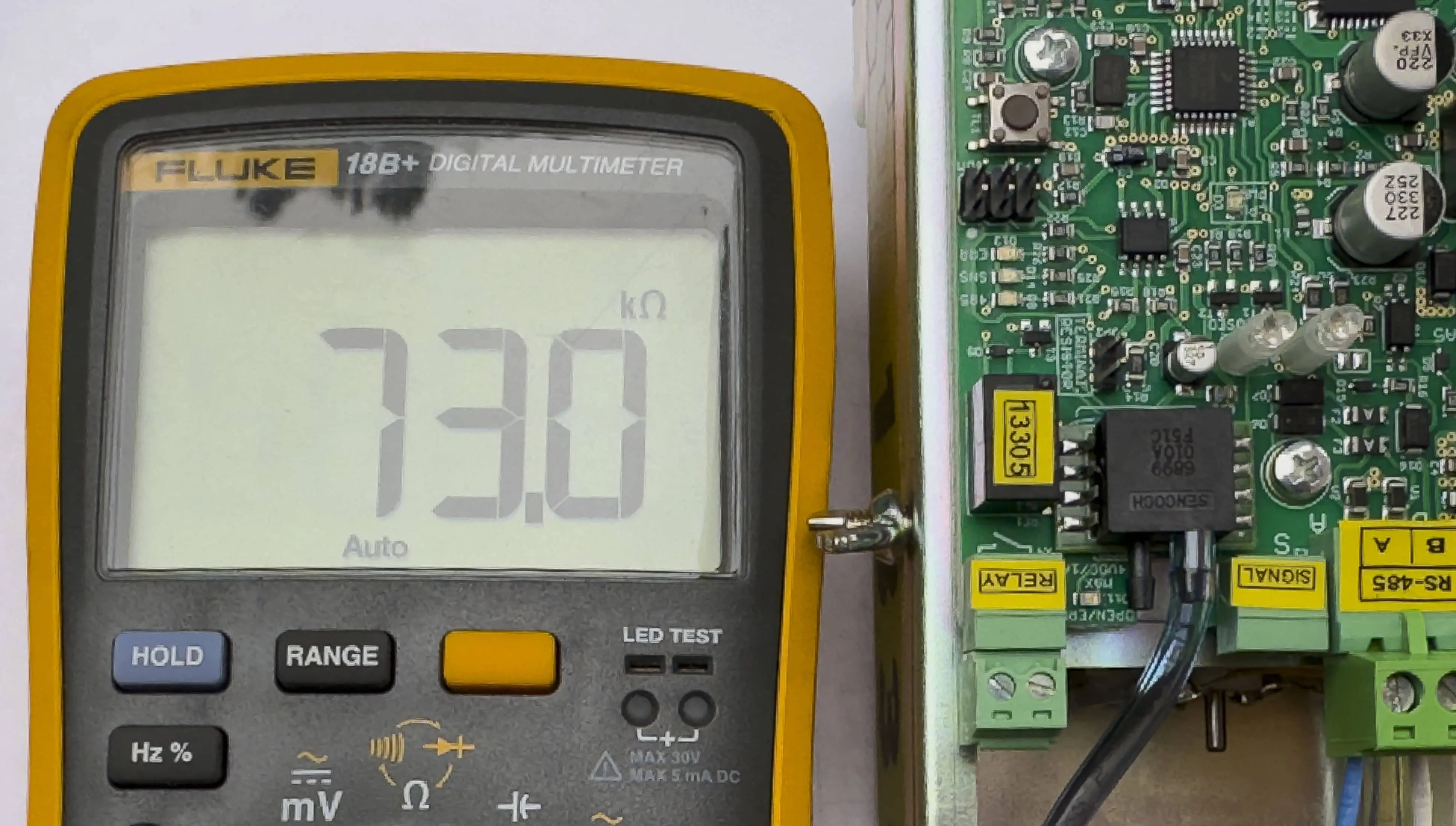
Resistor OFF: Approximately 73 kOhm (73,000 Ohm)
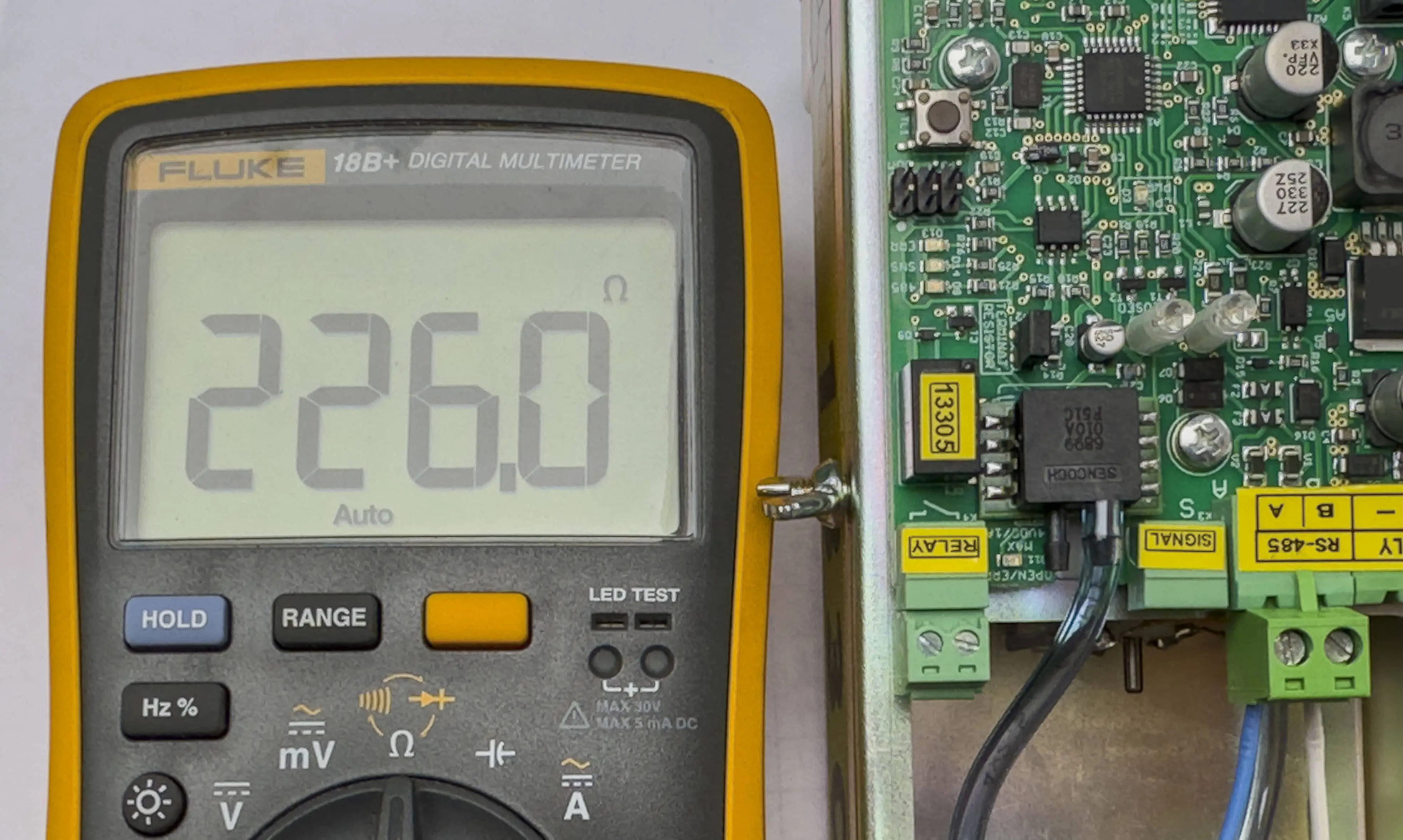
Resistor ON: Approximately 226 Ohm
At the greenBOX Nxt:
Connect the ohmmeter between the greenBOX Nxt's Modbus A and B wires.
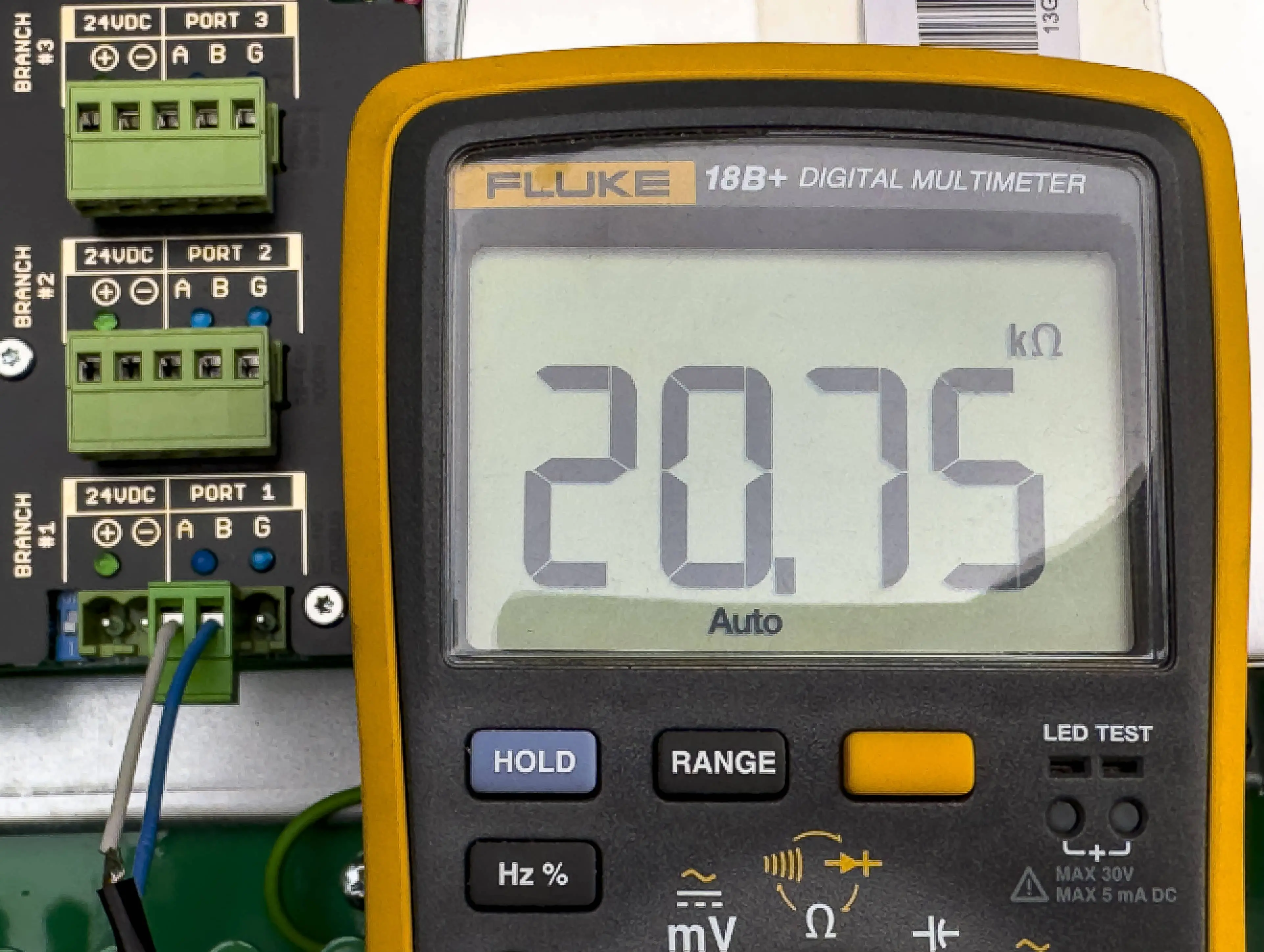
Resistor OFF: Approximately 20.75 kOhm (20,750 Ohm)
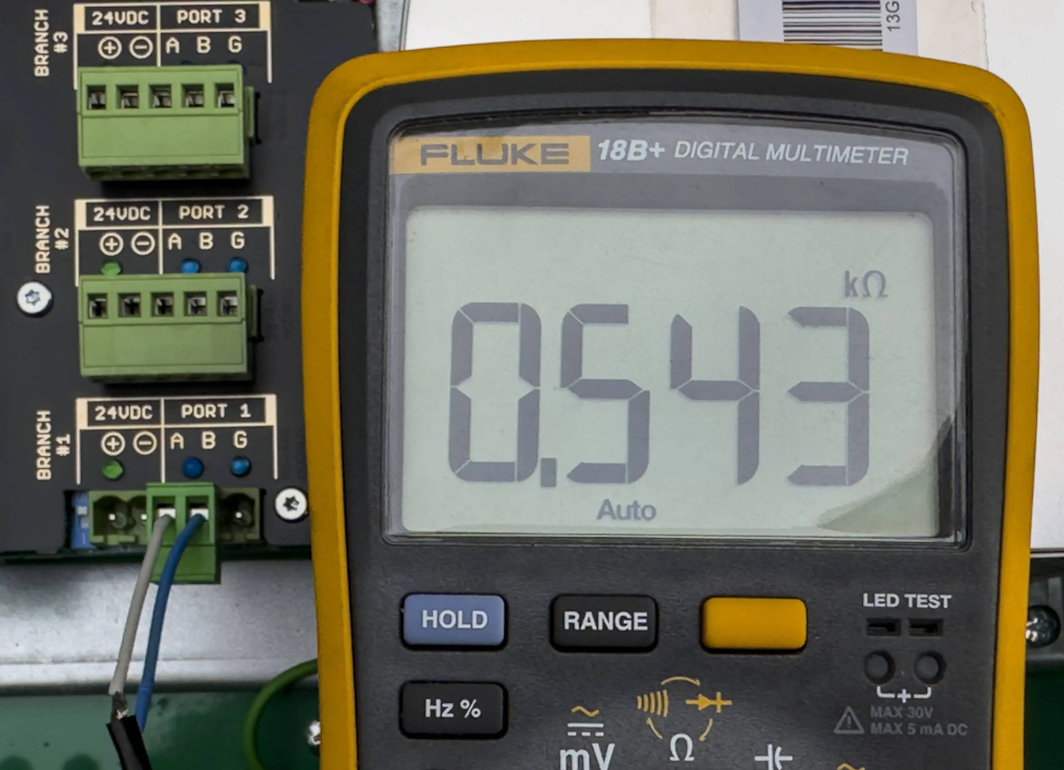
Resistor ON: Approximately 0.543 kOhm (543 Ohm)
Left: Gate TR OFF - Resistance measures approximately 73 kOhm. Right: Gate TR ON - Resistance measures approximately 226 Ohm
Left: Nxt TR OFF - Resistance measures approximately 20.75 kOhm. Right: Nxt TR ON - Resistance measures approximately 0.543 kOhm
Checking Daisy-Chained Gates
If you're unsure about the terminating resistor connection at the last gate:
Disconnect the Ecogate Master cable from the greenBOX port.
Measure resistance between Modbus A and B wires of the cable using an ohmmeter.
200-300 Ohm: Terminating resistor is connected.
700 Ohm or higher: Terminating resistor is NOT connected.
Note: Without a terminating resistor, the parallel resistance of gates is approximately:
2 kOhm for 10 gates
1 kOhm for 20 gates
700 Ohm for 30 gates
Remember: Proper termination is essential for system reliability. If you're unsure about any measurements, consult with Ecogate support or a qualified technician.
Conclusion
With this comprehensive guide, you're now equipped to install and set up your greenBOX Nxt system with confidence. From mounting the main unit to connecting gates in a daisy-chain and ensuring proper termination, each step plays a crucial role in optimizing your dust collection system's performance. Remember, attention to detail during installation lays the foundation for a reliable, efficient, and safe operation.
While the process may seem technical, taking it step-by-step will lead to a successful setup. If you encounter any challenges or need further clarification, don't hesitate to refer back to the specific sections of this guide or consult the full user manual available for download.
Thank you for choosing Ecogate for your dust collection needs. We're confident that with your greenBOX Nxt properly installed, you'll experience the full benefits of our On-Demand Control System. Happy installing!





Comments