


greenBOX Nxt Quick Software Setup Guide
- David
- Feb 7
- 14 min read
Updated: 4 days ago
Summary
Setting up your greenBOX system software is the final step to unlocking the full benefits of on-demand ventilation control. This guide walks you through the entire configuration process, from accessing the greenBOX remotely and adding ventilation systems to calibrating air velocity readings for optimal performance.
By following these steps, you’ll ensure that your system:
✔ Operates efficiently with automated gate control and intelligent airflow management.
✔ Maintains proper transport air velocity, preventing material buildup in ductwork.
✔ Optimizes energy savings, reducing electricity consumption and extending equipment lifespan.
✔ Provides real-time monitoring of power usage and cost savings.
Once calibrated, your greenBOX system runs automatically, adjusting to workstation activity for maximum efficiency and a cleaner, quieter, and more cost-effective work environment. Let’s get started!
Table of Contents
Setting Up Your greenBOX System Software
Step 1: greenBOX Remote Access via LAN or Internet
Step 2: Adding a Ventilation System
Step 3: Adding Workstations and Gates to Ventilation System
Step 4: Adding Ecogate Power Master VFD to Ventilation System
Step 5: Setting System Minimal Airflow
Step 6: Setting Duct System Cleaning Mode
Step 7: Tracking Your Electricity Savings
Step 8: Calibrate Air Velocity/Air Volume Readings, and Enjoy Fully Automated Ventilation System
Setting Up Your greenBOX System Software
Now that you've successfully wired your Ecogate system using our Quick Installation Guide, it's time to configure the greenBOX software. Just like the wiring process, we've designed the software setup to be straightforward and user-friendly. The interface is intuitive, functioning similarly to a smartphone or tablet, making navigation simple.
The best part? The greenBOX software is standardized across all systems, regardless of your shop or factory size. It has been rigorously tested in real-world industrial environments, ensuring reliability and consistency in operation.
Getting Started
Before diving into the setup, you'll need to input some basic information about your system:
A list of your workstations, including the diameter of gates (drops) and their ID numbers (printed on the gate motor enclosure).
Design drop air velocity to ensure proper system airflow.
Main duct diameter (for larger systems, also include the diameter of branch ducts).
Minimum required transport air velocity to prevent material buildup in the ducts.
The final step—calibration—optimizes the system’s performance by aligning it with your fan curve and fine-tuning the air velocity and volume readings. Detailed calibration instructions can be found in the "greenBOX Nxt Quick Calibration Guide"
This guide will walk you through the entire setup process, step by step. Let’s get started!
Additional Resources
For a visual guide, check out the article below (with videos) covering:
Software User Interface
Adding Gates
Adding VFDs
Warnings & Errors
PC and Interface Board Monitoring
Electricity Savings Monitoring
Step 1: greenBOX Remote Access via LAN or Internet
greenBOX Unboxed - Access on LAN Using Browser
For the initial setup, entering workstation names and other system data is more efficient on your computer than using the greenBOX touchscreen. While the touchscreen is convenient for making quick adjustments during fine-tuning, we recommend using your computer for the bulk of data entry.
Here’s how to access your greenBOX:
Local Network (LAN)
If your greenBOX is connected to your local network via an Ethernet cable, and your computer is on the same network, simply enter the greenBOX's IP address into your web browser. This will open the greenBOX user interface.
To find the greenBOX IP address:
Go to Menu → Monitoring → Computer → Networking → Right → Local IPv4 Address.
Remote Access (via LAN)
If your greenBOX is connected to the internet through your LAN, you can access it remotely using Tailscale VPN. For assistance with installing Tailscale on your computer and securely accessing your greenBOX remotely, please reach out to Ecogate Support at: support@ecogate.com
Direct Connection
If neither of the above options is available, you can connect a wireless keyboard and mouse directly to the greenBOX. Simply plug the keyboard’s USB receiver into the USB port on the black NUC computer located inside the greenBOX enclosure.
Once you’ve successfully established a connection, you’re ready to input your system data and proceed with the setup.

You can find the greenBOX IP address on the local network at Menu → Monitoring → Computer → Networking → right column IPv4 Address (10.0.6.3 in this case). The VPN internet address is in the left column IPv4 Address (100.74.139.98 in this case).
Giving Your greenBOX a Recognizable Name
A clear and descriptive name helps users quickly identify the correct greenBOX, especially in facilities with multiple units or locations. A well-named greenBOX also makes troubleshooting with technical support easier.
Recommended Naming Format
We suggest using this format: "greenBOX Model SerialNumber FactoryName"
Model: Indicates the greenBOX model (e.g., Nxt, Max).
SerialNumber: The unique serial number found on the greenBOX label.
FactoryName: The name of your factory or facility.
Example:
greenBOX Nxt 3223-031 Sweet Joinery

Give the greenBOX a helpful name, select Display Unit, select Timezone, enter Currency, and average electricity cost per kWh.
Additional Configuration Settings
While naming your greenBOX, take a moment to configure the following:
Units: Choose between IMPERIAL (for the USA) or METRIC (for most other regions).
Timezone: Select your local timezone to ensure accurate timestamps in the event log.
Currency: Enter your local currency for electricity cost savings tracking (more details in Step 7).
Average Electricity Cost per kWh: Input your average electricity cost to enable savings calculations (more details in Step 7).
Step 2: Adding a Ventilation System (Dust, Mist, or Fume Collecting)
greenBOX Unboxed - Adding Systems
Now, let's add a ventilation system to your greenBOX configuration. The system is flexible, allowing you to add multiple ventilation setups, each with its own VFD (Variable Frequency Drive) for independent fan control.
Key System Constraints
While you can add multiple systems, the main limitation is the number of gates that can be connected to the greenBOX.
Gate Limit: Each greenBOX Nxt has three Modbus ports, with a maximum of 24 gates per port. This limitation is due to power supply capacity.
Power Supply: Each Modbus port provides 24V DC output, is LPS (Limited Power Source) compliant, and has a maximum of 100VA (equivalent to 4A at 24V DC).
Safety: Each output is protected by a fast-acting electronic fuse.
How to Add a Ventilation System
Navigate to the greenBOX Menu.
Select "Systems Setup."
Click on "Add System."
Enter a recognizable system name, along with a one-letter system identifier.
Once added, you’ll be able to configure the ventilation system settings, including adding workstations, gates, and a VFD.

To add a ventilation system, navigate to the greenBOX Menu → "Systems Setup" and click on "Add System."
Step 3: Adding Workstations and Gates to the Ventilation System
greenBOX Unboxed - Workstations in greenBOX
greenBOX Unboxed - Adding Gate to System
greenBOX Unboxed - Smart Gate User Interface
Workstations and Gates in the Ecogate System
In the Ecogate system, a workstation can have one or more gates, offering key advantages:
Simplified Status Display: The greenBOX interface displays a single workstation icon that reflects the status of all its gates, making system monitoring easier.
Reduced Sensor and Labor Costs: Multiple gates in a workstation can share a single sensor, lowering equipment and installation costs. However, each gate can also have its own dedicated sensor for independent operation.
Automatic Modbus Addressing
Conventional HVAC and ventilation systems require manually setting unique Modbus addresses for each gate using DIP switches.
Ecogate simplifies this process:
Easy Gate Identification: Each gate motor has a clearly printed five-digit Gate ID number.
Automatic Address Assignment: Simply enter the Gate ID into the greenBOX, and the system will automatically detect the Modbus port and assign the appropriate address. This saves time and prevents configuration errors, particularly in larger systems or when adding gates later.
Adding Workstations and Gates
Access System Settings: Click on the system name under "Systems Overview" on the left side of the screen (or click the pencil icon on the dashboard) to open the system edit screen.
Navigate to Workstations: Select the "WORKSTATIONS" tab.
Create a New Workstation:
Press "ADD WORKSTATION".
Click the three-dot menu on the right.
Select “Edit Workstation” and enter a recognizable workstation name.
Add a Gate: Click on the gate icon.
Enter Gate Details: Fill in the Gate Driver ID number, Gate Diameter, and Design Drop Air Velocity.
Activate the Gate: Click "ENABLE". The greenBOX will discover the gate and assign its Modbus address.
Continue Adding Gates: Repeat this process for additional gates within the same workstation, or create new workstations as needed.
Important Tip
Start by adding workstations and gates closest to the fan, then work toward the farthest points in the duct system. This setup allows the greenBOX to optimize gate openings for maintaining minimum transport air velocities and improving system cleaning efficiency when using the "FROM END" duct option.

Enter a workstation name that users will recognize, and then click on the gate icon.

Fill in the Gate Driver ID number, Gate Diameter, and Design Drop Air Velocity, then click "ENABLE."
Step 4: Adding Ecogate Power Master VFD to the Ventilation System
Ecogate Setup Assistant - Power Master
greenBOX Unboxed - Adding ABB VFD
Before adding the VFD to the greenBOX system, you'll need to run the "Ecogate Setup Assistant" on the Power Master VFD's control panel. This process configures the VFD’s parameters for seamless Modbus communication with the greenBOX.
Important Note
During the initial "Ecogate Setup Assistant" run (automatically starts when the VFD is powered on for the first time):
Select the "greenBOX NXT or 12" model—this sets the VFD's Modbus address to 2.
If using multiple VFDs on the same daisy-chained Ecogate Master cable, select "greenBOX MASTER" and manually assign Modbus addresses 1, 2, 3, or 4.
Adding the VFD to the greenBOX System
Access VFD Settings:
In the greenBOX interface, click on the system name under "Systems Overview" on the left side (or click the pencil icon on the dashboard) to open the system edit screen.
Go to the "VFDs" Tab:
Select the "VFDs" tab.
Add a VFD:
Click "ADD VFD."
Enter VFD Details:
Provide a recognizable name for the VFD.
Select the Ecogate Power Master (ABB ACS580/ACS880) model from the list.
Enter the baseline power (start with the motor’s size in kW, as entered in the Ecogate Setup Assistant).
Select the maximum frequency (60 Hz in North America).
Enter the greenBOX Modbus port number where the Ecogate Master cable from the VFD is connected.
Enter the VFD’s Modbus address (usually 2, as set by the Ecogate Setup Assistant).
Enable the VFD:
Click "Enabled."
Within a few seconds, real-time data should appear from the VFD, including:
Frequency (Hz)
Power (kW)
Voltage (V)
Current (A)
The Power Master VFD is now fully integrated and ready for use with your ventilation system.

Enter a recognizable VFD name, select the Ecogate Power Master (ABB ACS580/ACS880) VFD model from the list, enter the baseline power, select the maximum frequency (60 Hz in North America), enter the greenBOX Modbus port number where the Ecogate Master cable from the VFD is connected, enter the VFD's Modbus address (usually 2), and click "Enabled."
Configuring Fan and Filter Pressure Transmitters
The Ecogate Power Master VFD includes pre-installed, wired, and configured Ashcroft pressure transmitters (4-20 mA output), ensuring seamless integration with the VFD’s analog inputs. This minimizes setup errors and saves installation time.
Setting the Pressure Range
Users only need to configure the pressure range:
Filter: 10" wc
Fan (VFDs up to 200 HP): 20" wc
Fan (VFDs over 200 HP): 50" wc
Steps to Configure:
Use a descriptive "Peripheral Name."
Select "Pressure" as the Sensor Type.
With the system OFF, set the zero display value:
Press CLEAR → Press SET.
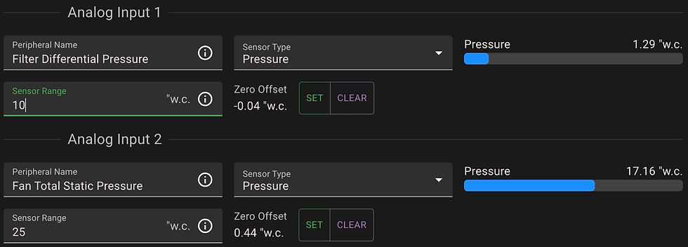
Set the pressure range: 10" wc for the Filter and 20" wc for the Fan (VFDs up to 200 HP) or 50" wc for the Fan (VFDs over 200 HP). Use a descriptive "Peripheral Name," select "Pressure" as the Sensor Type, and with the system OFF, set the zero display value by pressing CLEAR, then SET.
Step 5: Setting System Minimal Airflow
Maintaining Airflow and Preventing Material Settling
The greenBOX actively manages your system’s airflow by strategically opening and closing gates as needed and adjusting fan speed. This ensures the minimum required airflow is maintained, helping to prevent material from settling and accumulating inside your ductwork.
Setting Minimum Transport Air Velocity
In Step 3, you entered the "Design Drop Air Velocity" for each gate. The greenBOX uses this value, along with the gate's diameter, to calculate the Design Air Volume for each gate, workstation, and the overall system.
Minimum Transport Air Velocity
The minimum velocity required depends on the type of material in your system.
For sawdust, a common range is 3,000-4,500 feet per minute (FPM).
For specific recommendations, refer to "Industrial Ventilation, A Manual of Recommended Practice" or consult your local Authority Having Jurisdiction (AHJ).
For Longer, Larger Duct Systems: Use Duct Zones
For longer and larger duct systems, it is often necessary to divide the system into zones (branches) in the greenBOX and set minimum airflow levels for each zone individually.
📌 This guide focuses on setting the minimum airflow for the main duct only.
For instructions on setting up multiple duct zones, you can watch this YouTube video.

At "02. Main Duct Air Measurement", set the "Main Duct Diameter" for proper calculation of Minimal Airflow Air Volume.
Setting Minimum Airflow in the greenBOX Software
Access System Settings:
In the greenBOX interface, click on the system name under "Systems Overview" on the left (or click the pencil icon on the dashboard) to open the system edit screen.
Enter the Main Duct Diameter:
Scroll down to "02. Main Duct Air Measurement" and enter the main duct diameter.
Adjust Minimum Airflow Settings:
Scroll down to "03. Minimum and Maximum Airflow".
Use the slider in the software to set the minimum ratio of open gate area.
For efficient operation, choose the displayed "Minimum Air Volume" (in CFM or m³/h), which represents the minimum air volume needed to maintain adequate airflow.
Move the Minimum Slider:
Set the Minimum Slider to the minimum value of "Recommended Min. Value."
This corresponds to the Minimum Air Volume calculated in the previous step.
Select Minimum Airflow Mode:
Choose from the options below (LAST USED is recommended).
Enable Minimum Airflow:
Click "Enabled."

After entering Main Duct Diameter and Minimum Transport Velocity, move the Minimum Slider to the minimum value of "Recommended Min. Range" (highlighted with an orange slider background). Select Minimum Airflow Mode (LAST USED recommended), and click "Enabled."
Minimum Airflow Mode Options
LAST USED (Recommended): Prioritizes opening gates recently used, keeping frequently used gates ready.
FROM END: Prioritizes opening gates furthest from the fan, which can be beneficial for long or inefficient duct systems to maximize airflow.
NONE: Disables minimum airflow enforcement. Use this mode if your system does not require maintaining minimum transport air velocities (e.g., fume collection systems).
📌 Note: If you're interested in Maximal Airflow settings, stay tuned for a separate deep dive document covering that topic.
Step 6: Setting Duct System Cleaning Mode
How To Setup greenBOX Cleaning Mode
To keep your duct system clear and free of accumulated material (such as sawdust in a woodworking shop), the greenBOX includes a Cleaning Mode. Think of this as an extra layer of protection.
While greenBOX prioritizes maintaining minimum transport air velocity to prevent material buildup, airflow requirements can sometimes be underestimated—especially in complex duct systems with elevation changes or frequent elbows.
Recommended Best Practice
During the initial days of system operation:
✔ Inspect your main duct daily to verify that the minimum transport air velocity is correctly set.
✔ Enable and configure the Cleaning Mode to ensure optimal duct performance.

To set Cleaning Mode, select "Regularly" from the listbox, enable “Cleaning Run At Stop” (recommended), set Cleaning Interval, Cleaning Duration, and Cleaning Minimum Run Duration.
Configuring Cleaning Mode Settings
Access Cleaning Settings
In the greenBOX interface, click on the system name under "Systems Overview" on the left (or click the pencil icon on the dashboard).
Scroll down to "04. Cleaning" in the system edit screen.
Set Cleaning Mode
Select "Regularly" to initiate cleaning at scheduled intervals after the system starts.
Enable "Cleaning Run At Stop"
Activating this function runs a cleaning cycle before shutdown, ensuring ducts are clear when the system is not in use.
Enable Cleaning by Duct Zone (Optional)
For systems with gates assigned to specific duct zones, this option targets individual zones for increased cleaning efficiency.
Set Cleaning Interval
Adjust the time between cleaning sessions.
The default setting is 60 minutes (3600 seconds), but you can modify this based on your system's needs.
Set Cleaning Duration
Define how long the cleaning cycle should run.
Ensure the duration is sufficient for all gates to open and the system to run at full fan speed.
Observe the system and gate status during cleaning and adjust as needed.
Set Cleaning Minimum Run Duration
For systems that frequently start and stop, this setting prevents cleaning from running at every shutdown.
Configure a minimum system runtime required to trigger a cleaning cycle at shutdown.
(Optional) Adjust Fan Speed for Cleaning Mode
Navigate to "01. Fan Settings" → "Advanced Fan Settings".
Modify the fan speed specifically for Cleaning Mode and Clean Up (Cleaning at Stop).
Typically, 100% fan speed is used.

At "Advanced Fan Settings", you can adjust the fan speed specifically for Cleaning Mode and Clean Up (Cleaning at Stop). Typically, 100% fan speed is used.
Step 7: Tracking Your Electricity Savings
The greenBOX doesn’t just control your system—it also helps you track electricity savings. By monitoring your fan’s power usage, it calculates how much electricity (kWh) and money you’re saving.
Setting Up Cost and Currency
Go to the greenBOX menu and click on "greenBOX Settings."
Enter your local "Currency."
Calculate your average "Electricity Cost per kWh."
Divide your total electricity bill amount by the total kWh used.
Include additional utility charges to get the true cost.
For seasonal variations, use an annual average.

At "greenBOX Settings," enter your local Currency and average Electricity Cost per kWh.
Setting Baseline Power
Understanding Baseline Power
Baseline power represents the power your system would use without Ecogate—running at full speed all the time while providing the correct Design Air Volume to all drops.
Systems designed for 100% Total Design Air Volume
If your system is designed to provide proper Design Air Volume at each drop at 100% fan speed, enter the fan motor's power usage with all gates open.
You can find this value on the VFD display (select Manual Mode using the Power Master VFD door selector).
Systems that cannot provide 100% Total Design Air Volume
If your system cannot deliver the Design Air Volume at 100% fan speed to every drop, the baseline power will be higher than the fan’s motor size (kW).
In this case, contact Ecogate Support for assistance in calculating the correct baseline power based on fan laws.
Entering Baseline Power
Once calculated, enter the baseline power in the VFD tab under "Baseline Power."
Viewing Your Electricity Savings in Your Currency and kWh
Go to the greenBOX menu and select "Monitoring."
Click on the "GREENBOX" tab.
Run your system for a few days to accumulate measurable savings data.
Once complete, you’ll be able to monitor how much energy and money Ecogate is saving you!

View your electricity savings in your currency and kWh at the "Monitoring" menu, under the "GREENBOX" tab.
Step 8: Calibrate Air Velocity/Air Volume Readings & Enjoy a Fully Automated Ventilation System
Fine-Tuning and Enjoying Your Ecogate System
Now that your system is set up, it's time to calibrate the air velocity and air volume readings at the gates and main duct. This process, known as "ventilation system mapping to fan curves," fine-tunes your system for optimal performance.
📌 Detailed calibration instructions can be found in the "greenBOX Nxt Quick Calibration Guide"
A Fully Automated System
Once calibration is complete, your Ecogate system is fully automated and ready to go!
✔ Use your workstations as usual—the system will handle the rest.
✔ Activity sensors detect workstation usage, automatically starting the fan and dust collector.
✔ Unused gates close, while the system intelligently manages airflow to meet minimum transport air velocity requirements.
Key Benefits of Ecogate
🔋 Energy Savings: The fan operates at lower speeds, significantly reducing electricity consumption.
🔇 Quieter Operation: Lower fan speeds result in a quieter working environment.
🛠️ Longer Filter Life: Optimized airflow reduces wear and tear on filter bags, extending their lifespan.
📈 Scalability: The system’s adjustability and dynamic capacity make it easy to add more workstations in the future.


Comments